The Interferometric Wide (IW) swath mode is the main acquisition mode over land and satisfies the majority of service requirements. It acquires data with a 250 km swath at 5 m by 20 m spatial resolution (single look). IW mode captures three sub-swaths using Terrain Observation with Progressive Scans SAR (TOPSAR). With the TOPSAR technique, in addition to steering the beam in range as in ScanSAR, the beam is also electronically steered from backward to forward in the azimuth direction for each burst, avoiding scalloping and resulting in homogeneous image quality throughout the swath [1].
TOPSAR mode replaces the conventional ScanSAR mode, achieving the same coverage and resolution as ScanSAR, but with a nearly uniform Signal-to-Noise Ratio and Distributed Target Ambiguity Ratio.
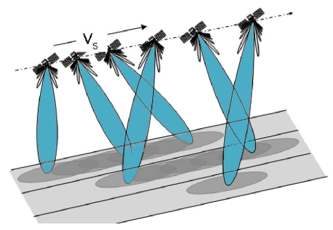
Figure 1: TOPSAR Sub-Swath Acquisition
The azimuth resolution is reduced compared to SM due to the shorter target illumination time of the burst. Using the sweeping azimuth pattern, each target is seen under the same antenna pattern, independently from its azimuth position in the burst image. By shrinking the azimuth antenna pattern, as seen by a target on the ground, scalloping effects on the image can be reduced. Bursts are synchronised from pass to pass to ensure the alignment of interferometric pairs.
IW SLC products contain one image per sub-swath and one per polarisation channel, for a total of three (single polarisation) or six (dual polarisation) images in an IW product.
Each sub-swath image consists of a series of bursts, where each burst has been processed as a separate SLC image. The individually focused complex burst images are included, in azimuth-time order, into a single sub-swath image with black-fill demarcation in between. There is sufficient overlap between adjacent bursts and between sub-swaths to ensure continuous coverage of the ground as provided in GRD products. The images for all bursts in all sub-swaths are resampled to a common pixel spacing grid in range and azimuth while preserving the phase information.

Figure 2: IW SLC Bursts andSub-Swaths
After burst and sub-swath merging, the full product can be created, as is the case for the GRDH products shown in Figure 3. The TOPSAR technique greatly reduces scalloping effects over conventional ScanSAR.

Figure 3: IW GRDH Product
The table below shows the main characteristics of the Interferometric Wide swath mode.
| Characteristic | Value |
| Swath width | 250 km |
| Incidence angle range | 29.1° - 46.0° |
| Sub-swaths | 3 |
| Azimuth steering angle | ± 0.6° |
| Polarisation options | Dual HH+HV, VV+VH Single HH, VV |
| Maximum Noise Equivalent Sigma Zero (NESZ) | -22 dB |
The table below shows the incidence and off-nadir angles for Interferometric Wide swath mode beams.
| Beam | IW1 | IW2 | IW3 |
| Off-nadir angles at min orbit altitude [°] | 27.53-32.48 | 32.38-36.96 | 36.87-40.40 |
| Incident angles at min orbit altitude [°] | 30.86-36.59 | 36.47-41.85 | 41.75-46.00 |
| Off-nadir angles at max orbit altitude [°] | 26.00-30.96 | 30.86-35.43 | 35.35-38.88 |
| Incident angles at max orbit altitude [°] | 29.16-34.89 | 34.77-40.15 | 40.04-44.28 |
[1] De Zan, F., & Guarnieri, A. M. (2006). TOPSAR: Terrain Observation by Progressive Scans. Geoscience and Remote Sensing, IEEE Transactions on, 44(9), 2352–2360. doi:10.1109/TGRS.2006.873853