Two successive operations are undertaken in order to obtain a Level-1C product from Level-1B products:
- Resampling of the Level-1B image to achieve an orthoimage in TOA reflectance.
- Calculations of cloud, cirrus and snow/ice masks for a tile in the Level-1C geometry.
Ortho-image generation
The different steps of this ortho-image generation are:
- Tiling module to select pre-defined tiles, which intersect the image footprint.
- Computation of resampling grids, linking the image in native geometry to the target geometry (ortho-image).
- Resampling of each spectral band in the geometry of the ortho-image using the resampling grids and an interpolation filter to compute the pixel radiometry.
Resampling grids computation
For SENTINEL-2 orthorectification, the resampling is complex and cannot be modelled by analytic transformation. Figure 1 shows the resampling grids that have to be computed between the source geometry of the native sensor (Level-1B geometry) and the target geometry (each ortho-image tile).
Figure 1: Resampling Grid
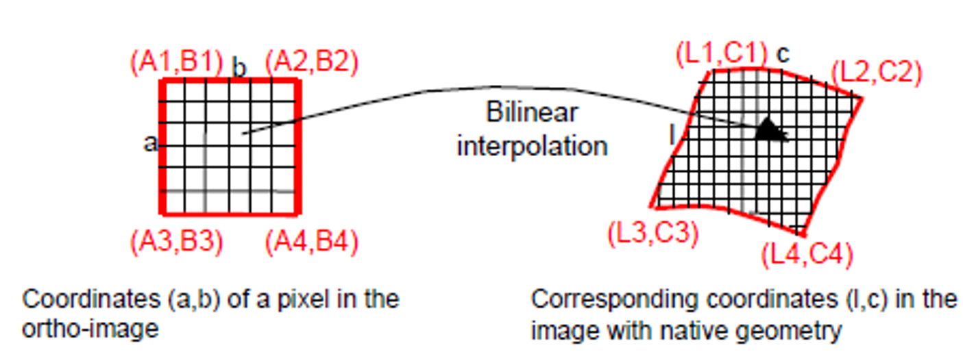
For each point (a,b) of the ortho-image, the coordinates (l,c) of the corresponding pixel in the native image is computed by bilinear interpolation of the 4 adjacent nodes (L, C), as shown in Figure 2.

Figure 2: Resampling grid interpolation
The geometric deformations are then supposed to be linear within a mesh; this approximation is acceptable if the step of the resampling grid is “small” enough.
Resampling grids computation is based in three steps:
- Transformation of the native coordinates into the DEM referential.
- DEM interpolation to get each grid point altitude.
- Image location computation to the source geometry by the physical model.
There is a grid for each band and each detector.
More details about the last DEM versions and how to access the data is available at https://spacedata.copernicus.eu/collections/copernicus-digital-elevation-model.
Radiometric Interpolation
The radiance values of the target point is computed based on the radiance of nearby pixels using cubic spline functions.
TOA Reflectance Computation
The numeric digital counts (CN) of each pixel image (i,j) and each spectral band (k) are converted in TOA reflectance (ρ). This conversion takes into account the equivalent extra-terrestrial solar spectrum (Es), the incoming solar direction defined by its zenith angle (θs) for each pixel of the image and the absolute calibration (Ak) of the instrument MSI.
The conversion equation is:
Equation 1: Top of Atmosphere conversion
where:
- CNk,NTDI is the equalized numeric digital count of the pixel (i,j) with NTDI, the number of SENTINEL-2 TDI lines, after removing the Level-1B offset (RADIO _ADD_OFFSET) added during the Level-1B generation
- Ak;NTDI is the absolute calibration coefficient
- Es is the equivalent extra-terrestrial solar spectrum and depends on the spectral response of the SENTINEL-2 bands
- The component d(t) is the correction for the sun-Earth distance variation (see Equation 2). It utilises the inverse square law of irradiance, under which, the intensity (or irradiance) of light radiating from a point source is inversely proportional to the square of the distance from the source.
Equation 2: Earth Sun distance
- t is the Julian Day which corresponds to the acquisition date (reference day: 01/01/1950)
- t0=2
- e is the eccentricity of the Earth orbit, e=0.01673
- n is the Earth orbit angular velocity, n=0.0172 rad/day
The parameters Ak and Es are provided by the GIPP and are also included in the ancillary data of the Level-1 products.
The sun zenith angles are determined at this level too. A sun angle grid is computed by regularly down-sampling the target geometry (Level-1C tile). The cosine of the zenith angle θs is defined at each point of the grid using the ground coordinates and the datation of the corresponding pixel acquisition. The azimuth angle is not processed here.
For Level-1C products, the noise model is also adapted to the new range of TOA reflectance radiometric values. The parameters (Ak,Es) of the Level-1B noise model are corrected using Equation 1 by replacing CNk with the Level-1B parameters Ak1B and Es1B.
The reflectance, often between 0 and 1, is converted into integer values, in order to preserve the dynamic range of the data by applying a fixed coefficient (10000 by default) called QUANTIFICATION_VALUE.
In order to avoid truncation of negative values, the dynamic range of Level-1C products (starting with the PB 04.00 introduced the 25th of January 2022) is shifted by a band-dependent constant radiometric offset called RADIO_ADD_OFFSET.
Before storage inside L1C (in a 16 bits integer format), a quantization gain and the offset are applied to the computed TOA reflectance (ρ).
L1C_DN = ρ * QUANTIFICATION_VALUE - RADIO_ADD_OFFSET
The L1C product's metadata includes the values for the QUANTIFICATION_VALUE and RADIO_ADD_OFFSET.
Please also note that:
- the radiometric offset is defined as a negative value.
- the radiometric offset will have no impact on the generation of the saturation value, as it will be added up after. Moreover, there will be no saturation due to this offset as the measured levels are far from the numerical saturation level (32767) for Level-1C data.
Computation of the Masks
The last operation to obtain the final Level-1C product is computation of the masks for a tile in the Level-1C geometry.
The Level-1C masks are in in raster format (JP2000, single-bit/multi-layer raster files) and are composed of:
- MSK_CLASSI (cloud, cirrus and snow)
- MSK_QUALIT (lost ancillary packets, degraded ancillary packets, lost MSI packets, degraded MSI packets, defective pixels, no data, partially corrected crosstalk and saturated pixels)
- MSK_DETFOO: the 12 detector footprints
The computation of these masks is explained and detailed in the Masks section.